Direct answer: diagnose the visible finish pattern first, then change RPM, feed, overhang, tool wear, coolant, or measurement method one variable at a time.
Use this guide for surface-defect diagnosis and correction paths; the surface-finish calculator handles theoretical Ra and N-class screening.
Diagnosing the Pattern
The first step is to identify what the marks on the part are telling you. Not all "bad finishes" are the same.
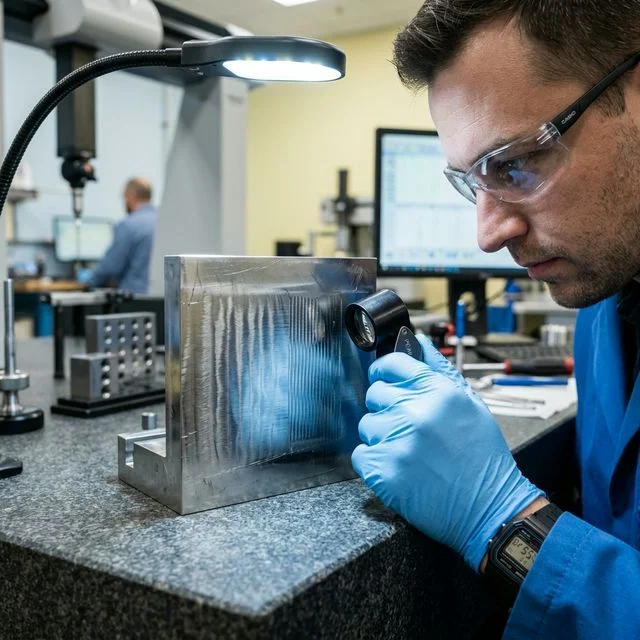
Chatter
Appearance: Distinct, repetitive, wave-like pattern. High-pitched screaming sound during cut.
Cause: Resonance. The cutting frequency matches the natural frequency of the tool/part.
Tool Deflection
Appearance: Tapered walls, gouges at corners, or "shadows" where the tool dwelled.
Cause: Tool is too long/thin, or cutting force is too high for the stiffness.
Troubleshooting Checklist
1. Solving Chatter
Chatter is a regenerative vibration. To stop it, you must break the harmonic cycle.
- Change RPM: Adjust RPM by +/- 10%. Often, slowing down isn't the answer. Speeding up to a "stable pocket" works better.
- Variable Helix Tools: Use end mills with unequal flute spacing to prevent resonance buildup.
- Increase Feed: Paradoxically, increasing feed load can dampen vibration by stabilizing the cut.
- Reduce Overhang: Shorten the tool stick-out. Stiffness decreases by the cube of length ratio ($L^3$).
2. Eliminating Feed Lines (Scallops)
In 3D surfacing, surface finish is determined by Stepover and Tool Radius.
Solutions:
- Use a larger ball nose end mill (increases effective radius).
- Reduce stepover (dramatically increases cycle time).
- Better Way: Use a Circle Segment (Lens) cutter for 5-axis finishing.
3. Fixing "Orange Peel" or Drag Marks
- Recutting Chips: Ensure coolant/air blast is actually clearing chips from the pocket.
- Built-Up Edge (BUE): Aluminum welding to the flute. Switch to polished flutes (ZL coating) and higher coolant concentration.
- Back Drag: In facing, if the trailing edge scratches the part, your spindle tram is out of square.
Surface Roughness Conversion
| ISO Class | Ra (µm) | Ra (µin) | Typical Process |
|---|---|---|---|
| N4 | 0.2 | 8 | Polishing / Lapping |
| N5 | 0.4 | 16 | Precision Grinding |
| N6 | 0.8 | 32 | Fine Milling / Turning |
| N7 | 1.6 | 63 | Standard Milling |
| N8 | 3.2 | 125 | Roughing |
Related Guides
If the issue is not a defect pattern but a required finish callout, compare it with the surface finish standards guide before changing the cutter path. For stability-limited finishes, check boring bar deflection and tool life before releasing the process.