The "Accuracy" Myth
Machine tool brochures often quote a single accuracy number, but acceptance and verification require more context. Under ISO 230-2, axis performance is evaluated from repeated direct measurements with defined calculation methods.
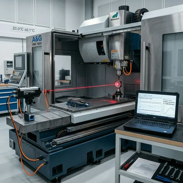
The Big Three Metrics
1. Positioning Accuracy (A)
How close the commanded position is to the measured position over the tested travel range.
Use report definitions exactly as stated by the test provider.
2. Repeatability (R)
How consistently the axis returns to the same commanded position under the same test conditions.
Interpret with run count, direction method, and uncertainty data.
3. Reversal Error (B)
Directional difference that appears when the axis approaches the same point from opposite directions.
Use together with mechanical condition checks (screw, bearing, coupling, compensation).
ISO 230-2 vs JIS B 6338
Be careful when comparing reports prepared under different standards frameworks.
- ISO 230-2: Defines a direct-measurement framework for evaluating positioning accuracy and repeatability on numerically controlled axes.
- Cross-standard comparison: Always align test setup, travel length, run count, environmental condition, and uncertainty treatment before comparing numbers.
Reading a Laser Calibration Report
Laser interferometer reports can be used for acceptance, periodic verification, and compensation review.
Look for trend shape: A consistent slope can indicate scale/compensation mismatch or thermal influence.
Look for directional split: A gap between forward and reverse traces can indicate reversal-related mechanical behavior that should be investigated.
Acceptance Limit Boundary
Acceptance limit note: ISO 230-2 defines the test and reporting method; the pass/fail limit must come from the purchase contract, builder specification, or customer quality plan. Do not compare two reports unless the travel range, target positions, approach directions, environment, uncertainty statement, and compensation state are aligned.
20°C Reference Condition
Treat 20°C (68°F) as the reference temperature for ISO 230-1:2012 and ISO 230-2:2014 interpretation, not as a complete universal setup by itself.
Thermal expansion is material-dependent, but for many steels the linear coefficient is on the order of 10–12 µm/m/°C. A simple estimate at +10°C over a 1 m structure yields roughly 100–120 µm of growth. For release decisions, confirm allowable gradients, soak/stabilization time, humidity, vibration control, compensation state, and measurement setup against the applicable ISO 230 procedure, builder test plan, contract, and uncertainty statement.
Related Guides
Use the ISO standards overview to confirm acceptance evidence, then use the ISO 230 reference table to choose the correct test family before reading an axis report. If the report changes a purchase decision, validate machine fit with the equipment selection calculator.